| ARINC 429 D Step by Step |
|
Image |
Explanation |
| 1 |
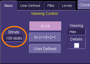 |
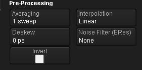
As a very first step when using the ARINC decoder, we need to set the bitrate. This is done in the Basic Tab. The values range from 12.5 to 100 kbits.
As these are the predominently used transmission speeds for ARINC 429, we also used them as min. and max. for the control. You can easily toggle from one to the other by using the "Set to Max" and "Set to Min" button of the Bitrate picker. |
| 2 |
 |
If there is the slightest doubt about the Bitrate, take a few seconds to make sure you have the right value. As the Bitrate governs the decoding, it is important to have it right from the onset.
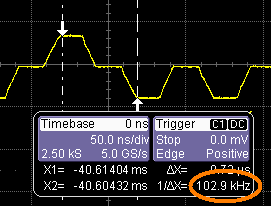
The simplest method is to use the Horizontal Relative Cursors. By positioning each cursor on equivalent positions of 2 consecutive bits, the 1/delta X read out will yield the Bitrate.
Here we chose to measure at the beginning of each bit plateau. The readout of 102.9 KHz can be rounded to 100 KHz and is good enough for the decoding algorithm. |
| 3 |
 |
Once this is done, we can turn on the Decoder by checking the View Decode in the main tab and... |
| 4 |
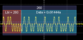 |
...see a first decoding of our signal on the trace. By default the decoder is set to decode in 8+24 mode. This means that the 32 bits message is decomposed into an 8 bits label and 24 bits of data. By the same token we can make sure that the Bitrate we measured is right: the red Label annotation should span the first 8 bits of the message. |
| 5 |
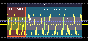 |
At this stage we can experiment with the controls in the Basic Tab, and see what other options we have. By checking the details, we see the individual BCD elements of the Data field. Here it becomes more apparent that the nibbles are swapped because the transmission order is LSN first. |
| 6 |
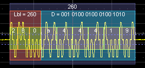 |
When selecting Binary instead of Hex, the Data fields change, but the low level details remain identical. |
| 7 |
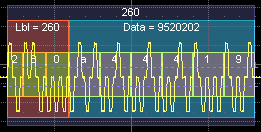 |
When selecting Decimal, the Data fields change accordingly. |
| 8 |
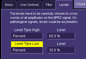 |
Before looking at other features, let's examine another fundamental control of the Decoder, the Levels, by switching to the Level Tab.
The Level selection is largely automated since by default both levels are set to be in percent of the amplitude. This simplifies the initial learning, but it is important to make sure the levels are set correctly to get a correct decoding. |
| 9 |
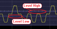 |
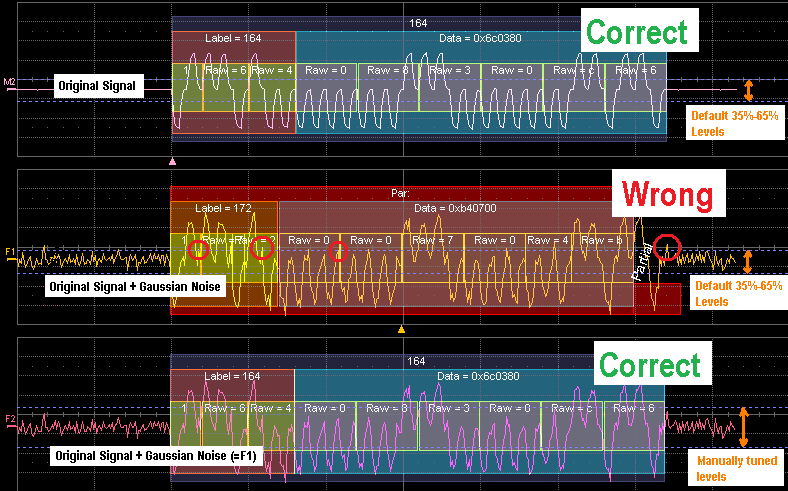
By default the levels are set to be at 35% and 65 % of full amplitude on the BPRZ signal. In most cases, this is a perfect choice and immediately leads to correct decode. |
| 10 |
|
However, in the real world, signals can be noisy, unbalanced or corrupted in some other ways. In these cases we would have to manually tune the levels to decode. In some cases it is easier to use the Absolute level setting, in Volts. It is also possible to have one level in % and the other one Absolute.
Click on the image to see more details. These examples show M2, F1 and F2. F1 and F2 are identical traces. Both of them are based on M2, with the same gaussian noise added. If you look closely at the images you will see that F2 decodes correctly thanks to the manually tuned levels. F1 is incorrect because the levels cross into the noise. |
| 11 |
 |
The previous example was just one way to overcome poor signals using manually tuned decode levels. Depending on the signal pathologies you can use various types of filters and/or smoothing techniques on the trace to still decode and read the contents of the messages. |
| 12 |
|
We have now covered the fundamental decoding controls, the bitrate and the levels. Once these values are correctly set, the decoder will execute reliably. We can then proceed to the study of higher level features offered by the tool with the assurance that the physical layer functions well. |
| 13 |
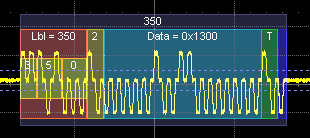 |
This is the second basic decode mode, the 8+2+19+2+1 mode. It is very similar to the 8+24 mode, with the addition of the SDS, SSM and Parity fields. It lends itself to the quick discovery of the messages in that structure. |
| 14 |
 |
We have now covered 2 tabs out of 4. The "Filter" tab will be the next object of interest. |
| 15 |
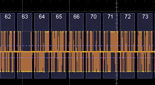 |
We will now turn our attention to the Message Filter. To that effect we will use longer message streams, i.e. here spanning 9 messages. In this image, no filtering has been used, and every ARINC Label is decoded. |
| 16 |
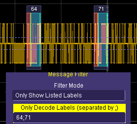 |
The Filter Mode "Only Show Listed Labels " is selected and two Label values are typed into the list 64 and 71 separated by a semi-colon. The resulting display shows the same stream as the previous item, however only messages 64 and 71 are decoded. Note that the table will also only list 64 and 71 lines.
This method allows the user to focus only on the messages he is interested in. For example 64 could be the Altitude because the Altitude Sensor is emiting strange values. |
| 17 |
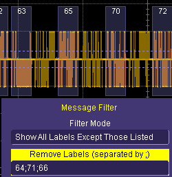 |
Conversely, the Filter "Show All Labels Except Those Listed" applies the opposite logic. This method is useful when one or more messages have a higher recurrence (shorter time interval) on the bus.
Here the filter unclutters the view, especially when the frequent messages are not the focus of the investigation. Also note that applying a filter increases the decoding performance, as well as the export performance." |
| 18 |
 |
We have now covered 3 tabs out of 4. The "User Defined" tab will be the next object to be explained. |
| 19 |
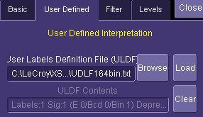 |
The "User Defined" tab contains the File Selection Widget necessary to pick a ULDF. The primary modus operandi is to have a Dedicated File for each ARINC 429 Equipment. When a given channel is connected to the Equipment and decoded, this File can be selected here.
The Browse button leads to the xTream File Picker. The Load button reloads the file when it has been edited in paralell. The Clear button clears the internal Database of USigD. |
| 20 |
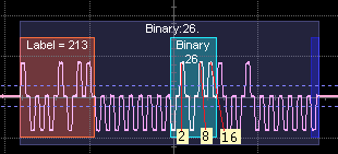 |
The User Label Definition File (ULDF) allows a customised annotation of subfields of the Data region in the ARINC message. A simple example is given here, for Label 213, with a 5 bit binary Signal positioned at offset 16 (0 based) , unitless and a resolution of 1. |
| 21 |
 |
The very reason for this mecanism is the incredible variety of usages of the Data Bits of the ARINC message. This is understandable as ARINC 429 concepts go back to the seventies. Aviation and avionics have tremendously evolved since then. The standard mecanisms explained above yield a good decoding of each message, with its Label, Parity Bit, SDI and SSM. However, the decoding of the Data Bits has blossomed into thousands of usages over the years. |
| 22 |
 |
In order to support this rich variety of messages, a uniform description language has been developed. Each user can then write its own Instrument decsription file. We will now look at the various encoding mecanisms used by ARINC: Binary, BCD and Enumerated, and see how each type can be described. |
| 23 |
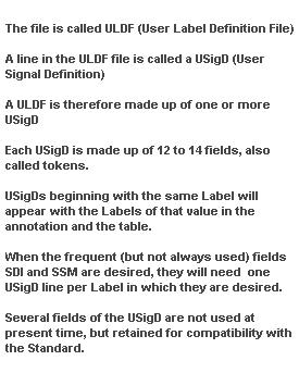 |
Before we do so, lets get familiar with a few abbreviations and abstractions that will make the reading easier.
It might seem odd that we use the word "Signal" for packets of bits within a message. This is due to the fact that the information embedded digitally into the words reflects an analog signal, such as the Altitude out of a piezometer, or the temperature out of a sensor.
Bearing this in mind, nothing precludes us from transmitting both an altitude and a temperature within the same message. |
| 24 |
 |
We will start with the simplest, Binary. Click on the picture to get an enlarged view and observe how the textual information in the white line drives the annotation on the trace. |
| 25 |
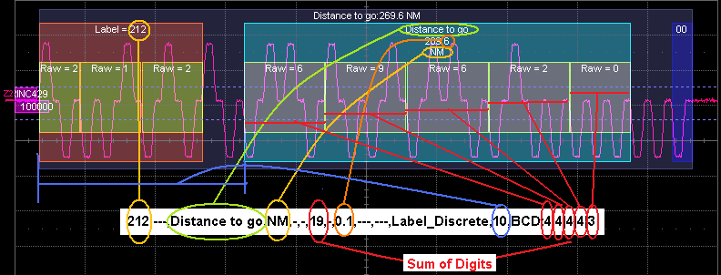 |
Now the same thing for BCD USigD. |
| 26 |
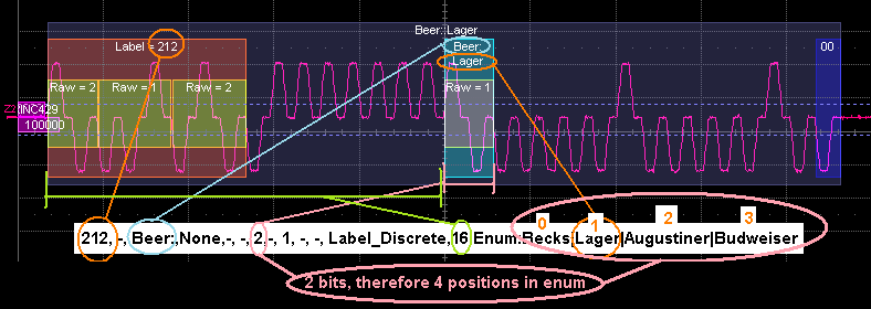 |
And finally for an Enumerated USigD. |
