| SENT and SENT SPC |
|
Link |
Explanation |
| 1 |
Latest SENT User's manual, Rel 8.3/2017 |
Latest SENT User's manual for Release 8.3/2017 Contains all necessary instructions for decoding Fast Channels as Nibbles and Words, as well as Slow Channels, filter and SCDF files |
| 2 |
SENT User's manual, Rel 7.1 |
SENT User's manual for Release 7.1. Contains all necessary instructions for decoding Fast Channels as Nibbles and Words, as well as Slow Channels. |
| 3 |
SENT Release Notes for Release 7.2 |
Contains the description of many improvements added in release 7.2. The decoding of the slow channels has been improved, the table organisation, the SCDF parser as well many other aspects |
| 4 |
SAE website for SENT specification
|
Unlike many other specifications freely available on the Internet, the SENT specification can only be purchased from the Society of Automotive Engineers (SAE). Furthermore, the distribution of the electronic document is limited by an electronic licensing system, allowing the reading of the document only on the machine for which the licensed has been purchased. The number of copies that can be printed with one license is also limited. Printing one page is not different from printing the entire document. It is therefore advisable to use the number of available prints to print the entire document. |
| 5 |
Example of SCDF |
Slow Channel Definition File (SCDF) Default File. This file can be cloned and edited for every type of sensor or SENT device. The file is then selected through the Filename Picker of the SENT Slow Channel Dialog, in the decoder's interface. |
| 6 |
Micronas_SCDF.txt
|
Customisation of default SCDF file for the Micronas HAL28xx sensors documented below. This file defines the "Slow Messages Definition Table" for 4 bit message IDs , as defined in the 2007 specification. In this case, the tables for manufacturer's names and error codes are not used. The Slow messages convey information about the Serial Numer, the Temperature, the System Clock and some other internal states. Examples of decoded streams are shown in items 3 and 11 of the Micronas measurements. |
| 7 |
Melexis_SCDF.txt
|
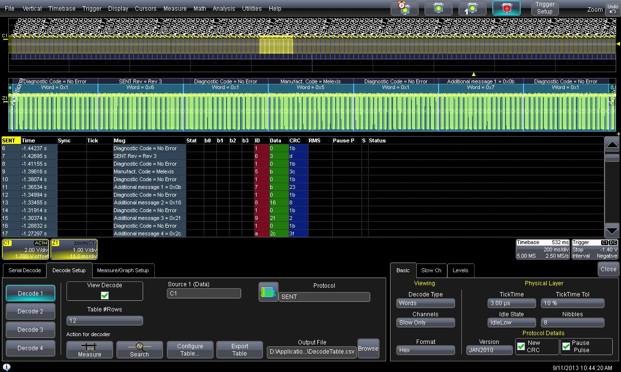
Customisation of default SCDF for the Melexis sensors documented below. This file defines the "Slow Messages Definition Table" for 8 bit message IDs , as defined in the 2010 specification. 4 Additional messages are defined. 4 messages IDs are interpreted with lookup tables: DiagnosticMessages, SENTSensorClasses, ManufacturerCodes and SENTRevisionCodes. |
| 8 |
HELLA_SCDF.txt
|
Customisation of default SCDF for the Hella Sensor documented below. This file defines the "Slow Messages Definition Table" for 4 bit message IDs , as defined in the 2007 specification. In this case, the tables for manufacturer's names and error codes are not used. The Slow Messages convey information primarily about the wafer position of the IC, as well as the lot number. |
| 9 |
Teledyne LeCroy SENT Data sheet and ordering information |
Link to the Teledyne LeCroy Data sheet for the SENT decoder |
| 10 |
Teledyne LeCroy SENT manual |
Link to the Teledyne LeCroy Manual for the SENT decoder |
| 11 |
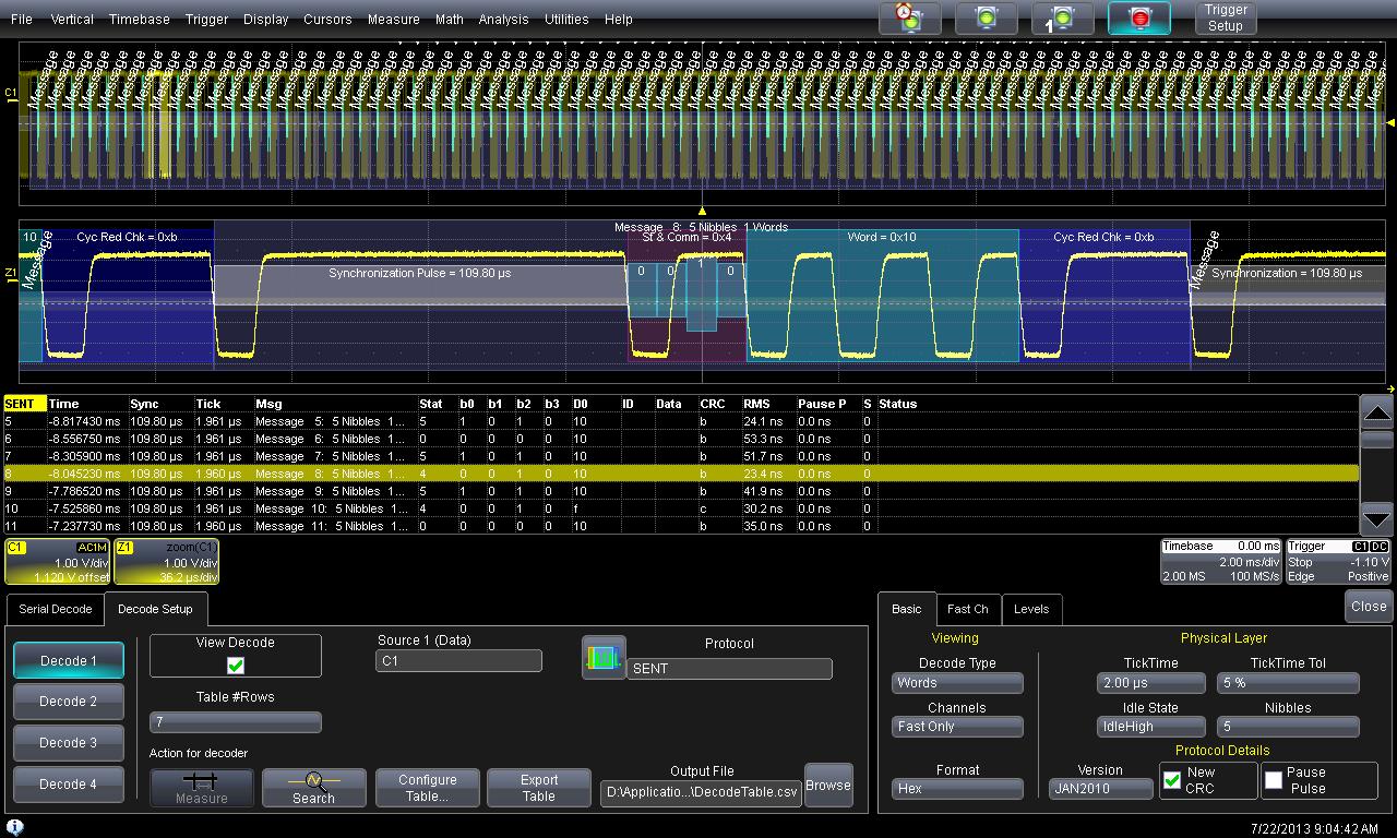
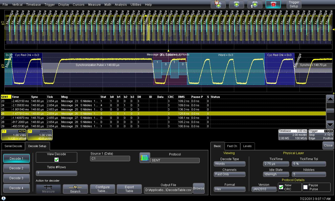
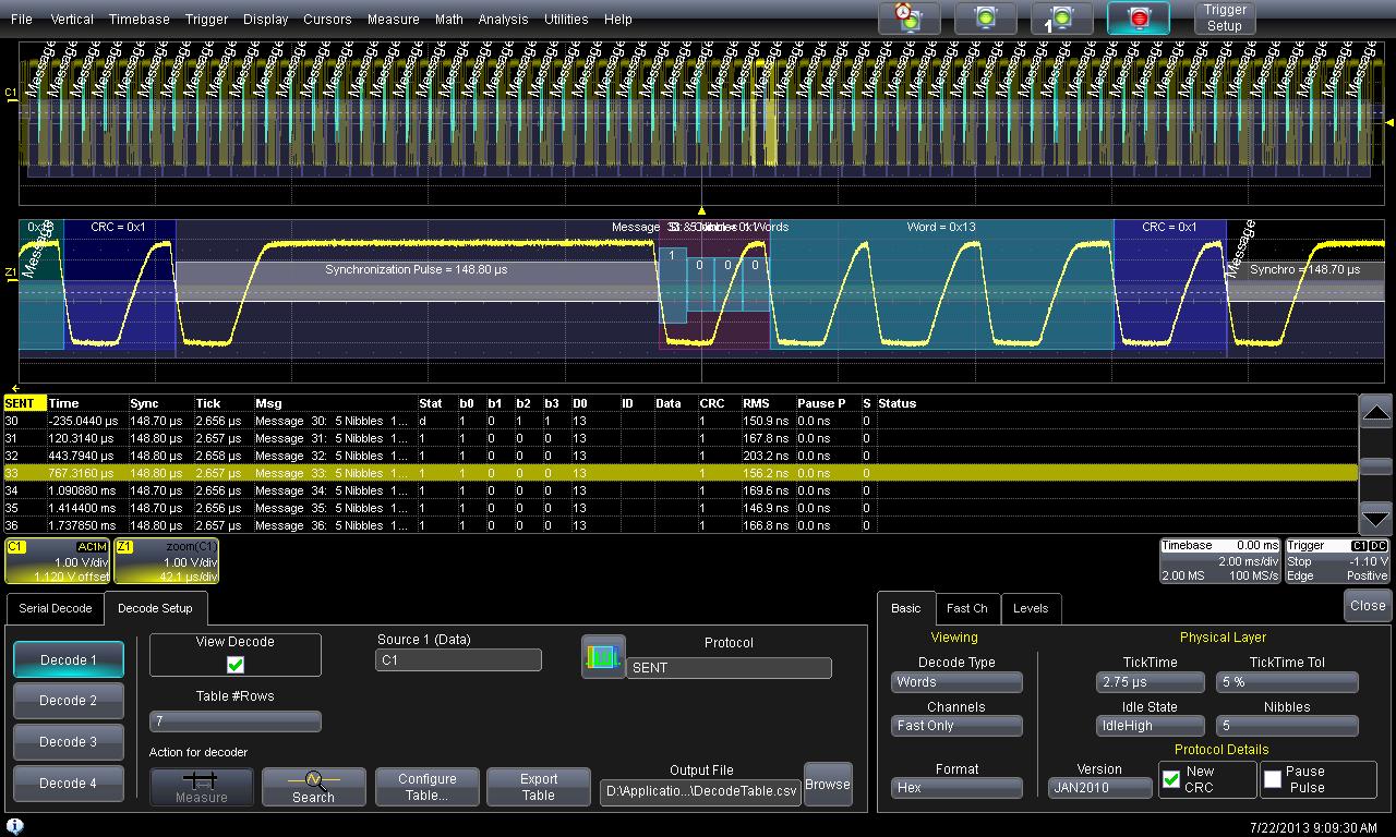
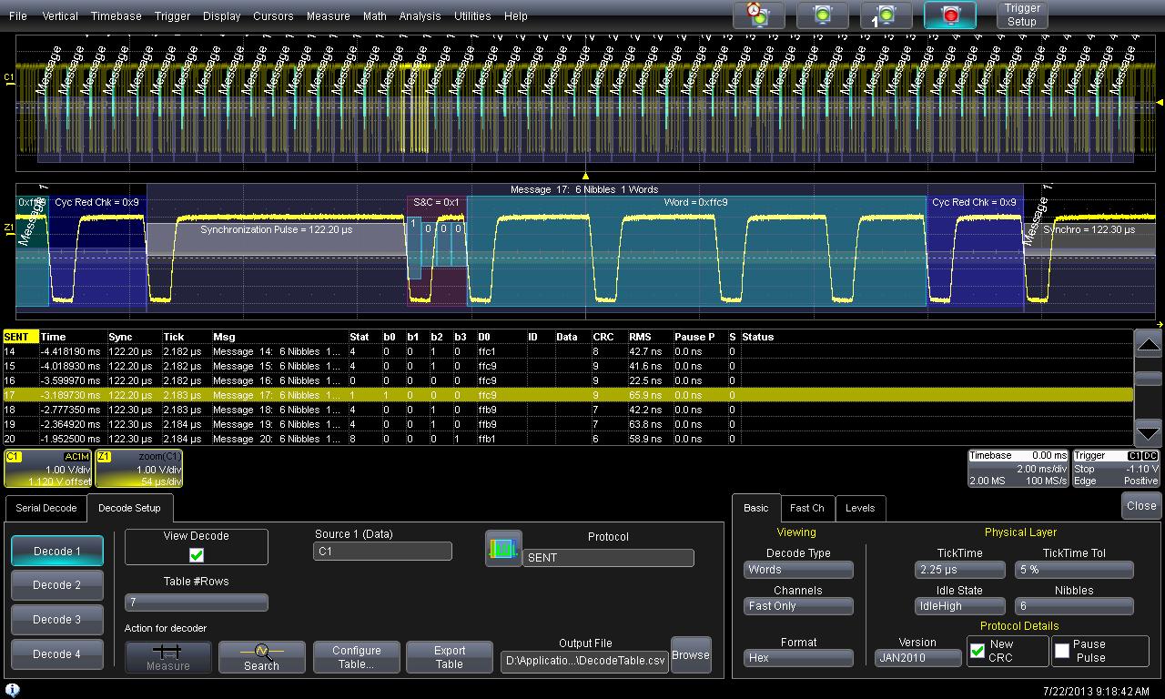
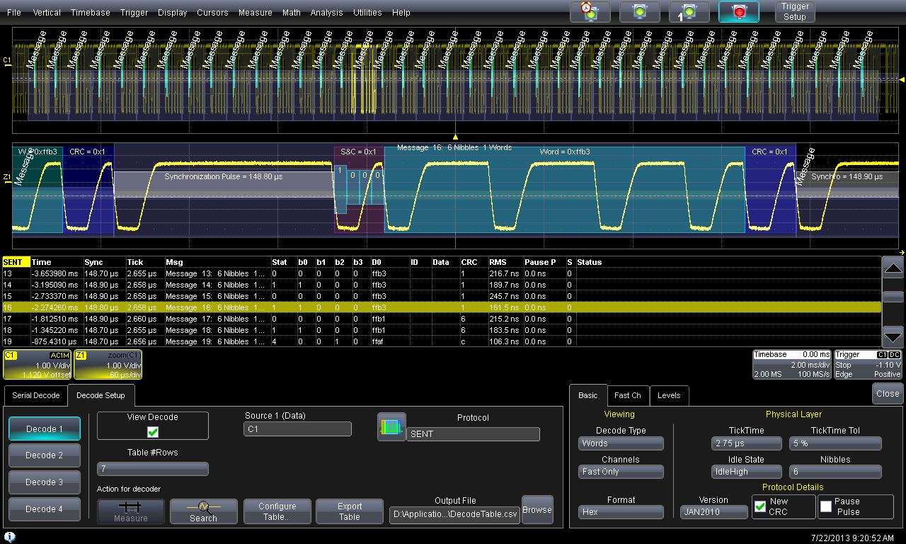
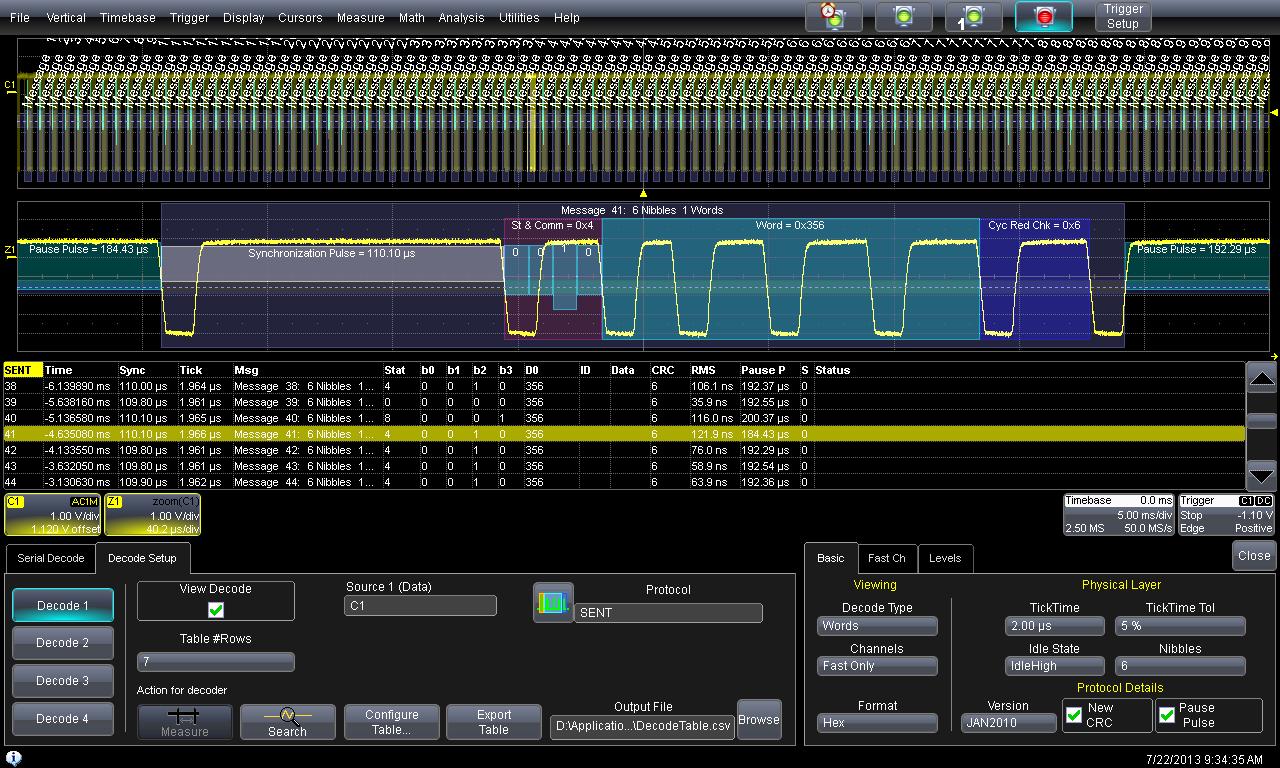
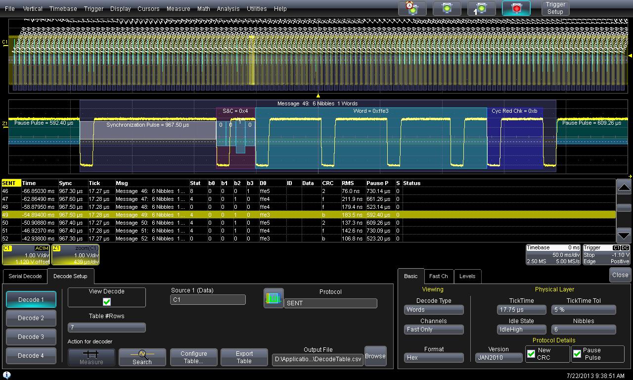
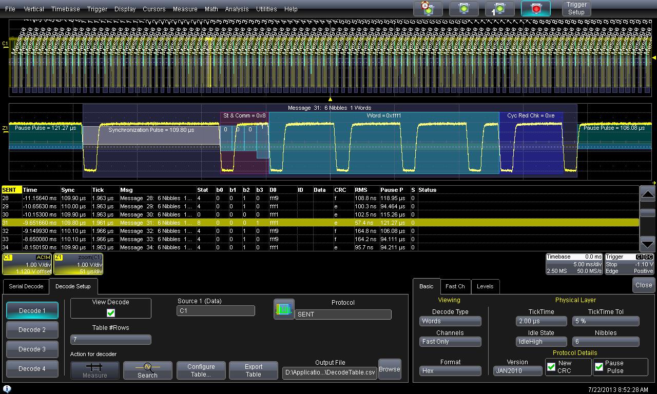
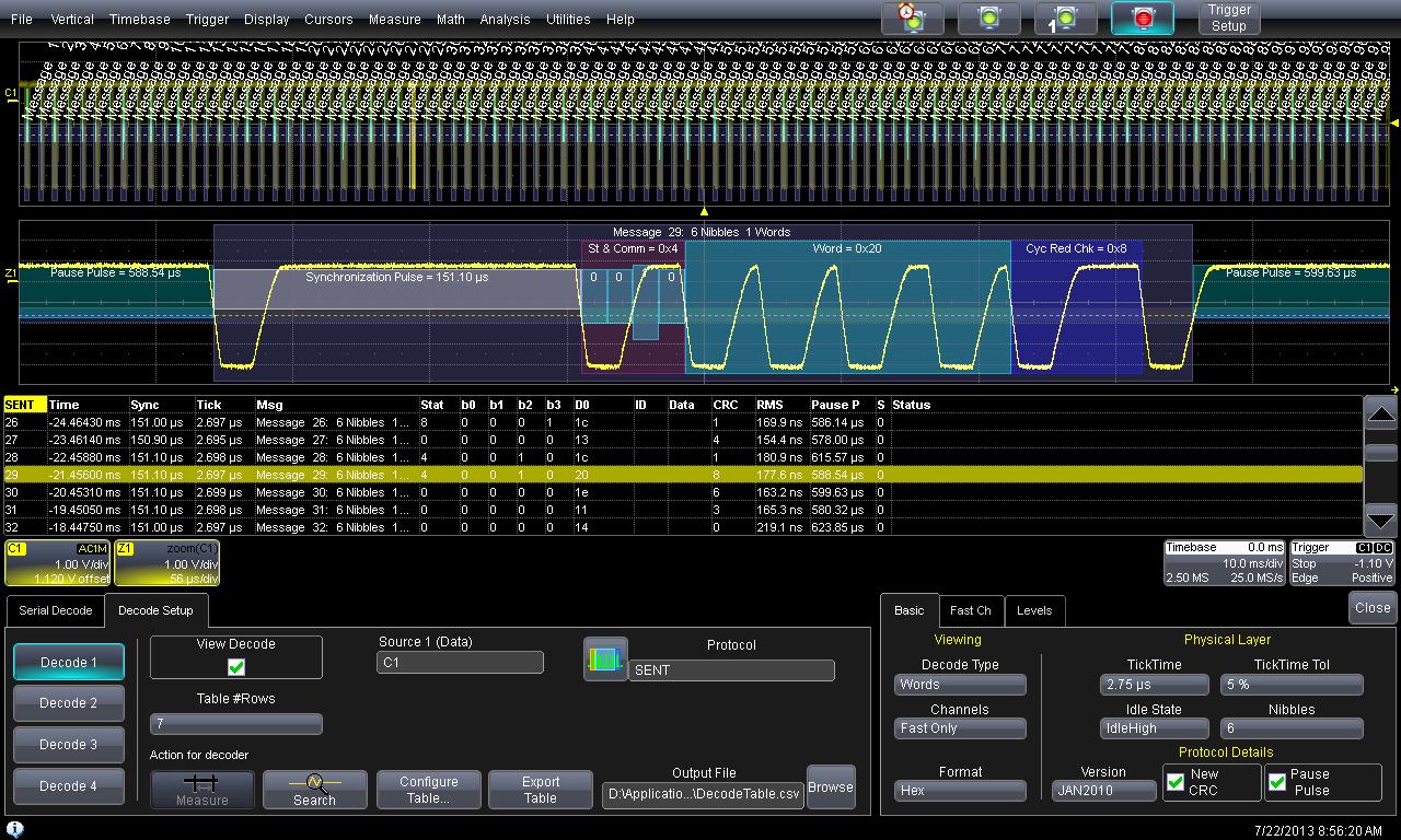
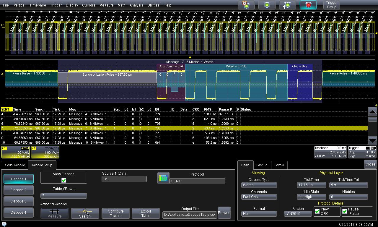
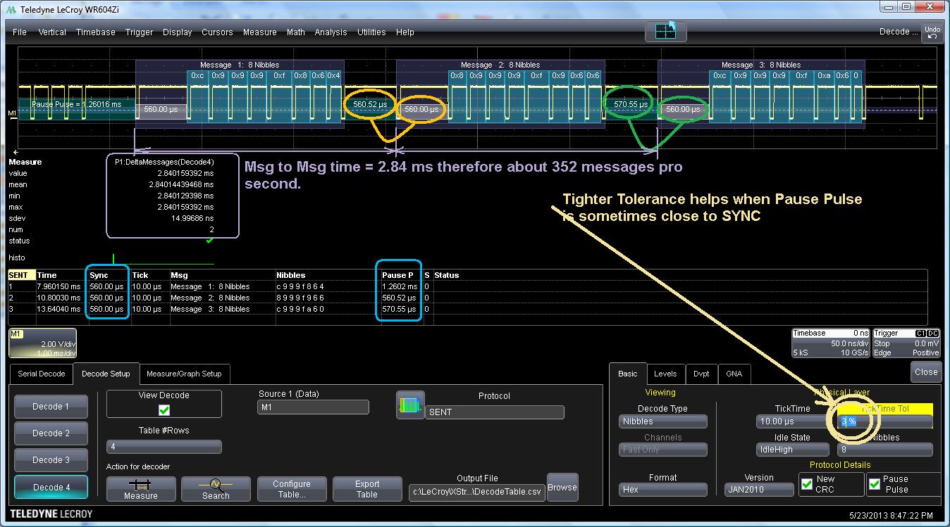
SENT Decode example |
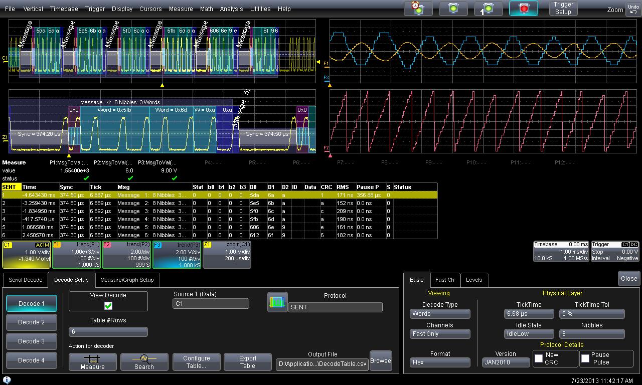
SENT Decode example (Fast channels only) |
| 12 |
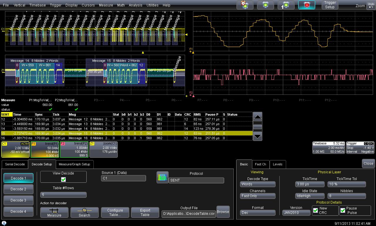
SENT Parameters robustness demonstrated |
This video shows the reaction of the SENT parameters to a loss of signal. When the SENT signal is lost, or heavily corrupted, the decoder stops operations and the table becomes completely empty. The parameters such as ColumnToValue, BusLoad, TimeAtMessage, MessageToValue reset their statistics. When the signal is reapplied to the input BNC, the entire computational chain resumes properly. In this case the signal is simply created/annihilated using a LAH10x inserted into Channel 1 |
| 13 |
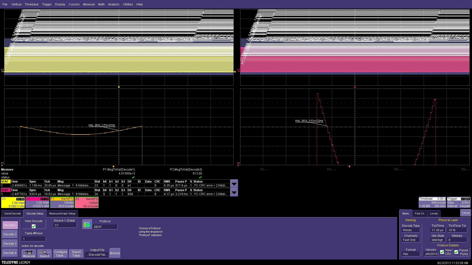
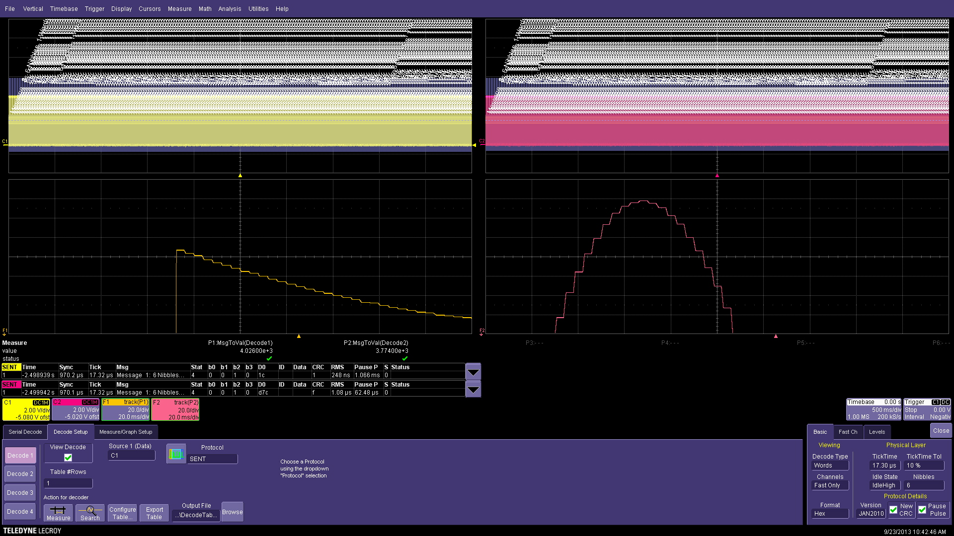
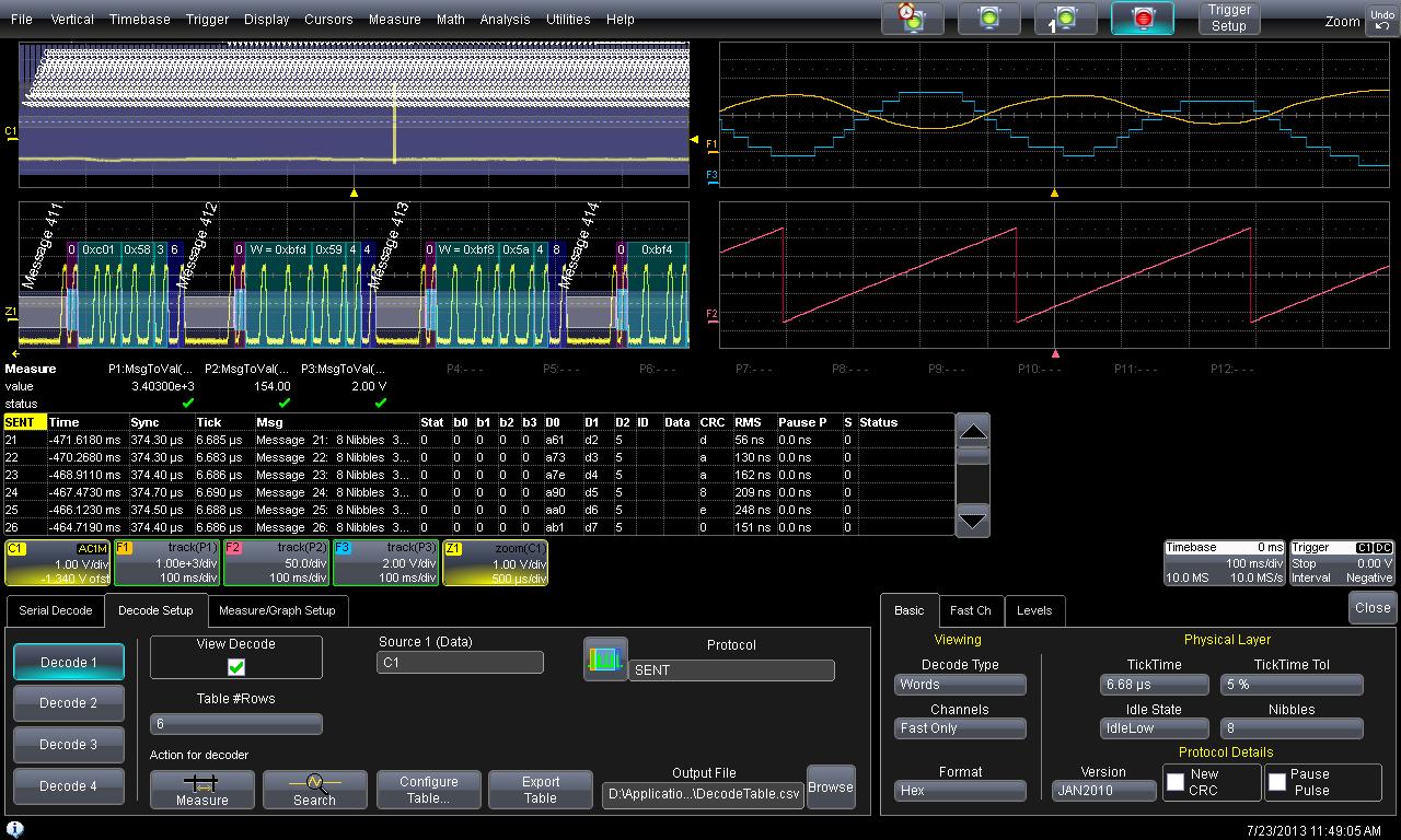
Multiple SENT decoding on Pressure Sensors |
Live experiment showing 4 pressure curves in paralell. The processing completely parallelizes the 4 decoders, the 4 MessageToValue and the 4 Trends monitoring the 4 MessageToValue. Using this method a sensors could be tested simultaneously, either using the osciloscope based Pass-Fail system or interrogating the oscilloscpe from a test PC. |


