| High-Level Data Link Control (HDLC) |
|
Link |
Explanation |
| 1 |
User's manual |
HDLC User's Manual. HDLC is decoded using dedicated settings of the general purpose decoder. In particular the NRZ or NRZ-S modes need to be selected, as well as the preamble synchronisation, CRC settings and bit un-stuffing mechanisms. Inquiries via info@lahniss.com |
| 2 |
 |
Exemple of a decoded HDLC Frame. This compact trace shows an entire Frame of 52 words. The violet regions, at the beginning and the end of the trace, represent the Start and End Patterns used by HDLC to mark the payload span. |
| 3 |
 |
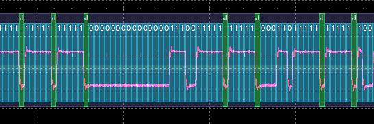
At the bit level HDLC uses stuff bits. The stuffbits do not carry any information and need to be ignored by the decoding algorithm. |
| 4 |
 |
Enlarged Start Pattern 0x7e. 0x7e translates to binary 0111 1110 and is visible in the analog trace, within the violet rectangle. Also note the stuff bit skip between byte 0x9f and 0x16. |
| 5 |
 |
Enlarged End Pattern 0x7e. The 2 bytes before the End Pattern represent the 16 bit CRC used by HDLC to insure the Frame integrity. |


